Next Generation LiDAR Surveying and 3D Mapping Solutions
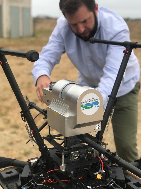
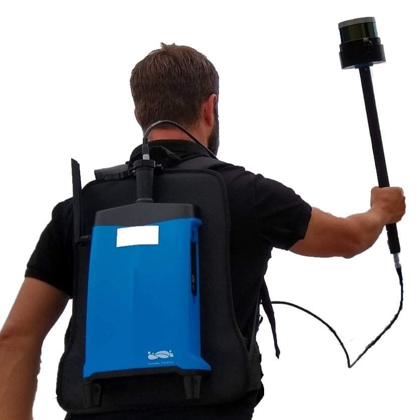
3D point clouds constructed from multiple laser scanning platforms, such as mobile handheld and UAV LiDAR systems, can provide comprehensive spatial descriptions of objects or regions of interest that would be difficult to generate using just a single laser scanning platform.
LIDAR Data Gaps are the Worst
Data holes occur where an object or surface with a mappable spatial structure can be found however was occluded from the surveying instrument(s) field of view during data collection. Information gaps of this type present troublesome or debilitating quality issues during the development of project deliverables or the running of operations that make use of laser scan data.
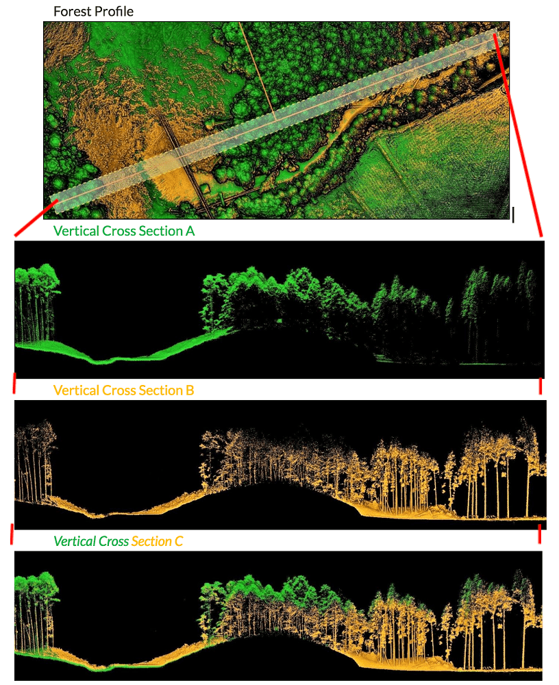
All laser scanning platforms have limitations that can lead to the formation of data holes. For example, airborne and UAV LiDAR point clouds often lack measurement data in the sub-canopy regions of forested areas. Conversely, ground-based terrestrial or mobile LiDAR systems capable of capturing the top-sides of forest canopies and tree heights.
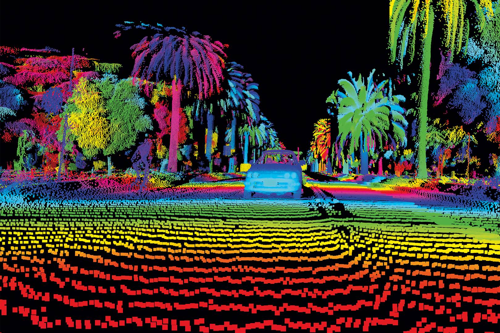
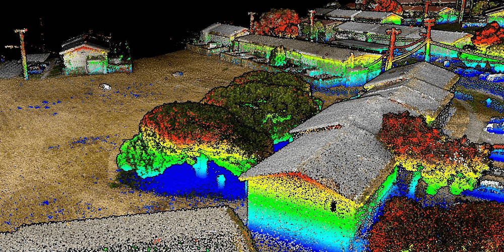
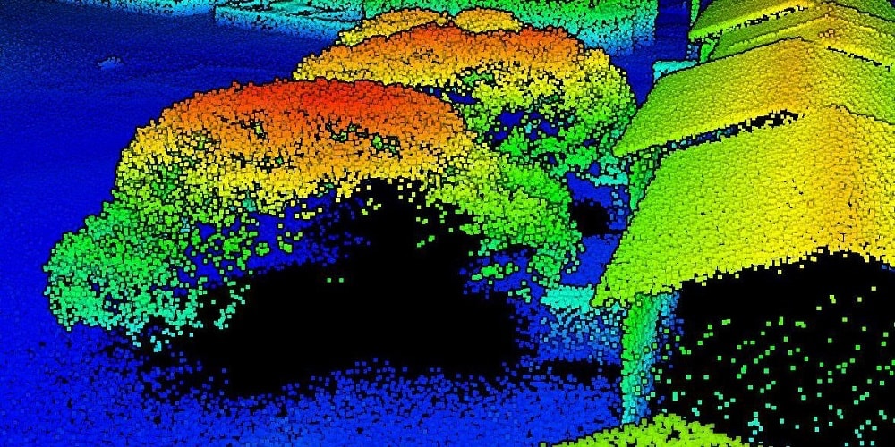
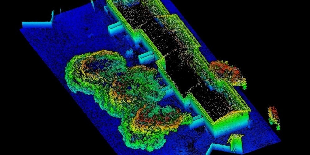
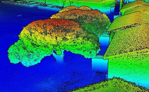
As a second example of a challenge, consider the typical airborne LiDAR dataset where the outer walls of structures are absent. The lack of information on building facades can low use during the generation of BIM objects for AEC applications or the generation of HD base maps. UAV- mounted LiDAR systems partially overcome the limitations with its improved side-looking or side-scanning capabilities. Terrestrial mobile laser scanning systems can offer point clouds that are complementary to aerial LiDAR datasets. In the images below you can see datasets captured from UAV and Mobile Handheld laser scanning platforms. Areas colored black represent data holes in the point cloud.
Filling Data Gaps with LiDAR360
In many instances, it is possible to resolve data hole-related issues by aligning LiDAR point clouds from more than one type of laser scanning platform. Data set alignment also referred to as co-registration, can be quickly carried out using GreenValley International’s LiDAR360 point cloud processing software. Two separate but spatially overlapping 3D point clouds area co-registered to the same target coordinate system using the Rectify Tool. The fitting of the individual datasets after the tool is run can be so tight that it becomes extremely difficult to identify areas where data holes exist in either of the included point clouds.
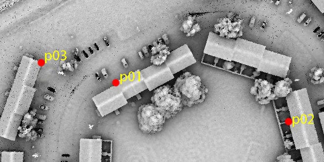
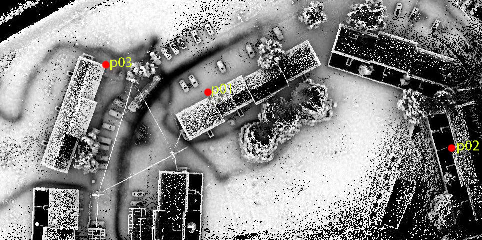
Rectify Tool in LiDAR360 allows users to pick a set of matching point pairs between two separate point clouds and then uses the X, Y, and Z directional offset values for each pair to find the transformation equation parameter settings needed to move the input data sets into alignment. Selecting the extreme outer edges to serve as alignment points can yield high-quality results when the Rectify Tool is run. Reference target spheres can also be included in the survey area and used to align overlapping point clouds. Matching point pairs (P01, P02, P03) found in the LiAir and LiBackpack datasets:
When separate but overlapping point clouds are aligned, some residual distance, or error, will remain between points that represent the exact same real-world location and object. The amount of space represents the error in the fit and should be minimized. Single and multi-dimensional error terms for each of the point pairs are reported in a tabular form that is displayed directly the Rectify Tool’s user interface. The user can also toggle individual point pairs on or off to find the combination of pairs that produces the lowest amount of error and generates the transformational equation that generates the best possible fit between the input datasets.
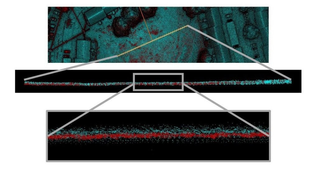
Tabulated error reports help to satisfy the quantitative aspects of quality assessment and quality control (QA/QC) reporting. But a simple visual inspection of aligned point clouds can be enough to convince professionals of a job well-done. Horizontal cross-sections can be generated using the Profile Tool in LiDAR360 and they allow users to quickly assess how well two separate and spatially overlapping point clouds.
With as few as just three pairs of matching or colocated points, LiDAR360’s Rectify Tool will calculate the transformation parameter settings required to accurately “stitch” two separate but spatially overlapping datasets together. This versatile tool can also be used fuse images to point clouds or align images to other images. LiDAR360’s straight forward user interface allows users to easily identify stitching points or target spheres during the alignment process and inspect the quality of the resultant fit between input datasets.
To find out more, please check the full text here.